The Vintage Voltage BMS provides battery management for Electric Vehicles (EV) and Energy Storage Systems (ESS). The VVBMS allows safe and simple reuse of Tesla battery modules, but has grown to support other OEM modules and custom Lithium packs. The BMS collects voltages, temperatures and controls cell balancing. It provides charger control for basic and smart CAN based chargers.
Main Features
- Emphasis on safety through monitoring, self-test and redundancy
- Directly connects with any Tesla Battery Modules and some other OEM modules
- Supports custom built LFP packs using the Vintage Voltage BMB (To be announced soon )
- Touch screen display option
- USB User Interface to a terminal program
- Controls up to 4 smart chargers with 4 separate presets
- Built in J1772 Interface
- Monitors battery current using one of 5 configurable dual range sensors
- Tracks the SOC (Fuel gauge)
- 4 contactors with varying degrees of economization. Built-in flyback protection.
- 4 relay controls with economization. Any output can be configured for any BMS function, simplifying wiring.
- 4 discrete inputs with programmable logic thresholds. Any input can be configured for any BMS function.
- Emphasis on safety through monitoring, self-test and redundancy
- Supports 4 Subpacks with 4 Strings
Supported Battery Modules
The VVBMS supports up to 4 separate module interfaces.
- Tesla Model S/X
- Tesla Model 3/Y
- Tesla Model 3/Y LFP – TI based
- LTC68xx based Modules including the Mercedes EQS, Thunderstruck Motors BSM or Vintage Voltage BMB
It can be ordered in different configurations, depending on you needs. Select option at checkout.
See Battery Module Identification for more details.
Hardware Specifications
| Parameter | Description | Range | Rating | Comments |
| 12V_IN | 12V always on DC power input | 11 to 14.5V | 5A Fused | Power to BMS internal supply as well as the 12V_RELAY output |
| 12V_RELAY | Relay Power Output | 11 to 14.5V | 5A Fused | Provides power to any external relays |
| CONT | Contactor outputs | 2 to 45V | 5A | Low side ports sink current through the contactor and 12V_RELAY. Built in fly-back protection. |
| INPUT | Analog or digital input | 0 to 15V | 33k load | Used for switch inputs. Configurable thresholds of 3.3, 5V, 9V and 12V |
| I_IN | Current sensor inputs | 0 to 5V | 22k load | Used to connect LEM dual range hall effect current sensors |
| LCD | Interface to external LCD | 0 to 5V | Provides 5V power and I/O to the VV LCD. |
UI
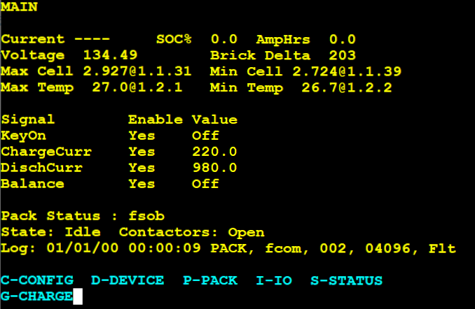
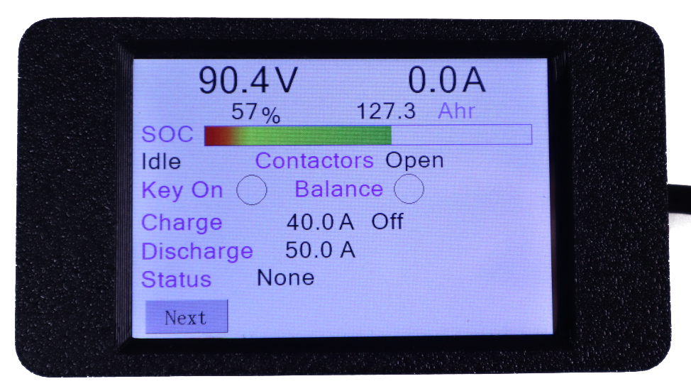
There are 2 user interfaces to the BMS, a serial terminal and an LCD touch screen. A Bluetooth phone application is in development.
The serial terminal is the main user interface that must be used for setup and configuration. The LCD is intended for in product use and only displays some high level pack information.
Subpacks and Strings
The VVBMS supports up to 4 battery boxes with 4 parallel stings of cells in each box.
- The separate battery boxes are called Subpacks and the parallel modules are called Strings.
- A String must be to a sequential series of modules, from a communications perspective.
- There can be up to 4 Subpacks and each can contain up to 4 Strings
- The Strings can be in ascending or descending voltage order.
Current Sensors
| Part # | Description |
| DHABS/15 | Dual 60/600A |
| DHABS/118 | Dual 30/350A |
| DHABS/124 | Dual 75/500A |
| DHABS/133 | Dual 75/750A |
| DHABS/137 | Dual 75/1000A |
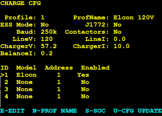
Smart Chargers and Inverters
| Manufacturer | Description | Model |
| Thunderstruck Motors | TSM2500 | Any |
| Elcon and Comptable | Onboard Chargers | Any CAN Based |
| Victron Inverters | Inverter Charger | MultiPlus-II |
| EG4 | Inverter Charger | 6000XP (Coming soon) |

EV Example
